
سبد خرید شما خالی است!
دسته بندی ها


INTRODUCTION
I like Atmel tinyAVRs because they are tiny computers that I can (almost) wrap my head around. The Atmel ATtiny4/5/9/10 are the cheapest in the tinyAVR line, and they come in two packages - SOT23 pictured above, and an even more stupendously small 2mm x 2mm USON package. This article will talk about programming these little chips. Though they may be tiny, they are still quite capable, and the right choice for many projects.
I’ve written about tinyAVRs before, and you can take a look at some of the articles before to get a feel for them.
- Talking to MMA7660 using I2C and ATtiny85
- Talking to Ultrasonic Distance Sensor HC-SR04 using an ATtiny84
- Serial Communications with the ATtiny84
One fundamental difference in programming ATtiny10 versus the above is that the former requires TPI (Tiny Programming Interface), which we will explore below.
THE CIRCUIT
To keep things interesting, we will program the ATtiny10 to drive a common cathode RGB LED. Here’s the schematic:

Above, you can see that the R, G and B leads of the LED are connected to PB0, PB1 and PB2 pins of the ATtiny10. You can also see the connections for the Tiny Programming Interface, which makes use of three signals - TPICLK, TPIDATA and RESET. The traditional MOSIin not connected. The pins are arranged in an indentical order to the standard 2x3 ICSP header. Another thing to remember is that TPI requires a 5V signal - 3.3V won’t cut it. (But after programming, your circuit can run at a lower voltage.)
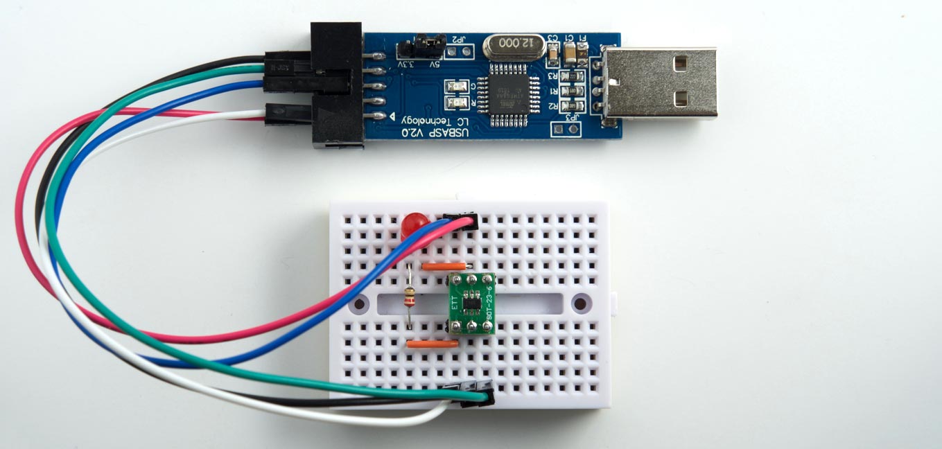
Here’s what it looks like, hooked up:

I used an SOT23 to DIP adapter above so I could use the chip on a breadboard. To plugin the Atmel ICE 2x3 header on a breadboard easily, I used a handy AVR ISP adapter PCB - an open source design you can order from OSH Park.
PROGRAMMING WITH ATMEL STUDIO 7 AND ATMEL ICE
I have written before on using Atmel Studio 7 and ICE for programming tinyAVRs. The setup is similar here, except that we need to use TPI as the programming interface. Once the project is setup and compiled, here’s what the device programming settings look like:

As you can see above, the interface is TPI and the target voltage is read in as 5V, and the signature 0x1E9003 matches that of ATtiny10 from the datasheet. Use the Program option under Memories to upload the code, and you’re done.
I’ll say it again: The combination of Atmel Studio 7 and ICE is a fabulous toolset for programing Atmel microcontrollers. A long term Mac user, I was so impressed by this combination that I bit the bullet, took a pickaexe to my frozen wallet, and broke out the hard cash to buy myself a license of Windows 10 (ugh) and Parallels (wow), so I could use these tools from the comfort of my Macbook and OS X. I wish that Atmel Studio was cross platform, but then I also wish that the Aliens land soon. I ain’t holding my breath for either.
NOTE
The RGB LED connections interfere with TPI programming. So you need to disconnect the LED (just pull the ground) during programming.
PROGRAMMING WITH USB ASP
I wanted to explore a cheaper option than Atmel ICE for programming the ATtiny10. I found some evidence (How is your Polish?) on the web that the cheap USB ASP programmer can be made to support TPI. But so far, I haven’t been able to make it work. I’ll update this section if I manage to do it.
In my view, it’s better to buy an Atmel ICE if you are working with their chips. They offer just the PCB for USD 35 if you are on a budget, and are brave enough to make your own cables.
THE CODE
The first thing you want to set is the clock speed. The ATtiny10 doesn’t have any fuses related to that, so you need to set that in the CLKPS register. The default is a prescaler of 8 which puts it at 1 MHz, but we want to run it at 8 MHz.
// Set CPU speed by setting clock prescalar:
// CCP register must first be written with the correct signature - 0xD8
CCP = 0xD8;
//  CLKPS[3:0] sets the clock division factor
CLKPSR = 0; // 0000 (1)
In the code, you want to ensure that F_CPU is set to 8 MHz so calls like _delay_ms() work correctly.
// define CPU speed - actual speed is set using CLKPSR in main()
#define F_CPU 8000000UL
The way we’re going to light up the RGB LED is to supply the correct PWM frequency to each channel, based on the colors. I’ve chosen these amazing colors for the LED, and they are stored in program memory as follows:
// cyan, magenta, orange, purple, yellow
const unsigned char red[]   PROGMEM = {  0, 255,  255, 127, 255};
const unsigned char green[] PROGMEM = {255,   0,  127,   0, 255};
const unsigned char blue[]  PROGMEM = {255, 255,    0, 127,   0};
The PWM for each channel is set in an interrupt function (more on setup below), which turns the channels on/off based on an 8-bit PWM counter variable:
// interrupt for Compare A
ISR(TIM0_COMPA_vect)
{
	// turn on/off according to PWM value
	if (pwmCount > rgb[0]) {
		PORTB &= ~(1 << PB0);
	}
	else {
		PORTB |= (1 << PB0);
	}
	if (pwmCount > rgb[1]) {
		PORTB &= ~(1 << PB1);
	}
	else {
		PORTB |= (1 << PB1);
	}
	if (pwmCount > rgb[2]) {
		PORTB &= ~(1 << PB2);
	}
	else {
		PORTB |= (1 << PB2);
	}
	// increment PWM count
	pwmCount++;

	// increment interval counter
	counter0++;
}
When the above function is called 256 times, we would have completed one cycle of the PWM. The interrupt is setup as follows:
// set up Output Compare A
// WGM[3:0] is set to 0010
// prescaler is set to clk/8 (010)
TCCR0A = 0;
TCCR0B = (1 << 1) | (1 << WGM02);
// set Output Compare A value
OCR0A = 39;
// enable Output Compare A Match interrupt
TIMSK0 |= (1 << OCIE0A);
In the above code (Yes, you need to read the datasheet!) we setup the 16-bit Timer0 of the ATtiny as follows:
- Set timer prescaler to divide by 8.
- Enable CTC mode for OCR0A.
- Set OCR0A value for comparison.
- Enable Output Compare A interrupt.
What the above does is to generate an interrupt every time the 16-bit counter value matches OCR0A. For the values chosen above, that happens every or 39 microseconds. So mutiply this by 256 and you get your PWM cycle = 0.01 seconds, or 100 Hz, which is fine to drive LEDs without flicker.
In the main code, the LED color is changed at regular intervals as follows:
// main loop
while (1)
{
  // change color every N cycles
  if(counter0 % colorInterval == 0) {
    colorIndex = (colorIndex + 1) % nColors;
	// set current RGB value
	rgb[0] = pgm_read_byte(&red[colorIndex]);
	rgb[1] = pgm_read_byte(&green[colorIndex]);
	rgb[2] = pgm_read_byte(&blue[colorIndex]);
  }
}
colorInterval is set to 32768, which gives an interval of 39 us * 32768 = 1.27 seconds. You can also see above how the colors are read in from program memory.
IN ACTION
Here you can see the ATtiny10 in action, changing the colors of the RGB LED every second or so. (I put a tape on the LED because I was going blind staring at it all day.)
DOWNLOADS
You can get the complete source code for this project here:
https://github.com/electronut/attiny10-rgb-hello
This article describes how to program the ATtiny10, Microchip's diminuitive 6-pin processor, using the Arduino IDE. It's a great chip for building small gadgets and wearables, or designing interface logic for other projects, and it really lives up to its "tiny" name:

The following sections explain how to program the ATtiny10 in C, and how to download programs using a low-cost ISP programmer. It also illustrates some simple applications with example programs.
Introduction
If, like me, you like using the simplest possible chip for each application, the ATtiny10 will appeal to you [1]; it's a 6-pin processor, about the same size as an 0805 SMD resistor, and it costs about 35p/35¢. It packs in the following features:
- Internal 8MHz clock, by default prescaled to 1MHz.
- Three I/O lines.
- Two 16-bit PWM analogue outputs.
- Three 8-bit analogue inputs.
- An analogue comparator.
- A 16-bit timer with input capture and an event counter.
- A watchdog timer.
- 1024 bytes of program memory, 32 bytes of RAM, and no EEPROM.
All of these features will be familiar to users of the larger AVR chips. Here's the pinout (using Spence Konde's design conventions):
The internal oscillator is accurate to within 10%, but you can calibrate it in software to within 1%. You can configure RESET as a fourth I/O line, which prevents further programming, but I don't cover that in this article.
To work with the ATtiny10 on a breadboard you can mount it on a SOT23 breakout board, such as the one available from Sparkfun [2].
Programming the ATtiny10
Unlike the SPI protocol used to program the larger AVR chips, such as the ATmega328 in the Arduino Uno, the ATtiny10 uses a programming protocol called TPI (Tiny Programming Interface) which needs only five wires. Fortunately Thomas Fischl's excellent USBasp programmer supports this protocol [3]; you can build your own, order one from his site, or they are widely available on eBay [4], Banggood [5], etc. I recommend getting one with a 10-pin to 6-pin adapter for ISP programming. The current versions of the Arduino IDE support the ATtiny10, so you can program it in C and upload programs as easily as with the other AVR chips. Since an Arduino core would use up almost half of the available program memory the best way to program it is to access the registers directly, and I give an overview of how to do this in the section Alternatives to core functions below.
Here are step-by-step instructions for programming the ATtiny10; it will work with the Arduino IDE versions 1.8 and upwards:
- Download the ATtiny10Core hardware configuration from my repository on GitHub ATtiny10Core.
- Copy it to the hardware folder in your Arduino folder in your Documents folder. If there isn't already a hardware folder there, create one first.
- Restart the Arduino IDE.
This should add an ATtiny10Core heading to the Board menu.
- Enter your program into the Arduino IDE editor.
For example, try the Blink example program given below.
- Connect the USBasp to the ATtiny10 as shown in the following diagram:
Connecting the USBasp programmer to an ATtiny10.
- Choose Board from the Tools menu, and select the ATtiny10/9/5/4 option under the ATtiny10Core heading; it's the only option.
- Choose the chip you want from the Chip menu; for example ATtiny10.
- Choose USBasp from the Programmer option on the Tools menu.
- Choose Upload to upload the program.
The LED should blink at 0.5Hz.
Here's my test setup on a mini breadboard:
Examples
نوشتن نظر
نام شما:نظر شما: توجه : HTML ترجمه نمی شود!
رتبه: بد خوب
کد امنیتی را در کادر زیر وارد نمایید:


. Theme developmed by tnm-group.com